I’ve had a couple of Garrett turbochargers laying around for some time now, a GT2056V from a E60 525d and a GT2260V from a E46 330d Euro4 to be specific. I originally bought these for my 320d as upgrade-turbos, but with so many other projects and stuff to do, i just haven’t got the time to swap in a bigger turbo. I’m working on my summer car at the moment, and it needs an actuator to control a flap/valve, so i thought why not borrow one from these turbos as they’re just wasting space at the moment.
The Actuator
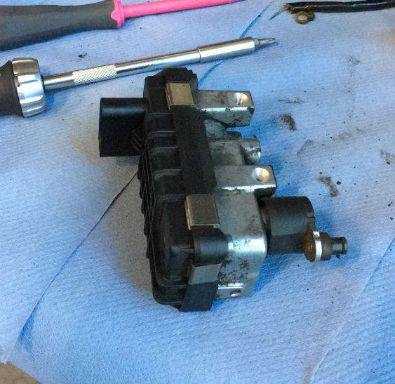
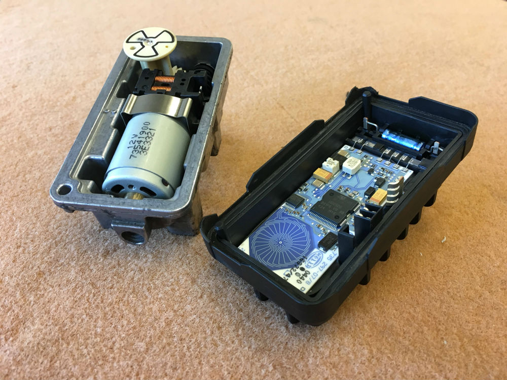
I dismantled the actuator from the GT2056V, took it apart, and gave it a quick cleanup. Looking inside, everything looked OK. No excessive wear on the mechanical parts, and no broken solder joints or melted components on the circuit board.
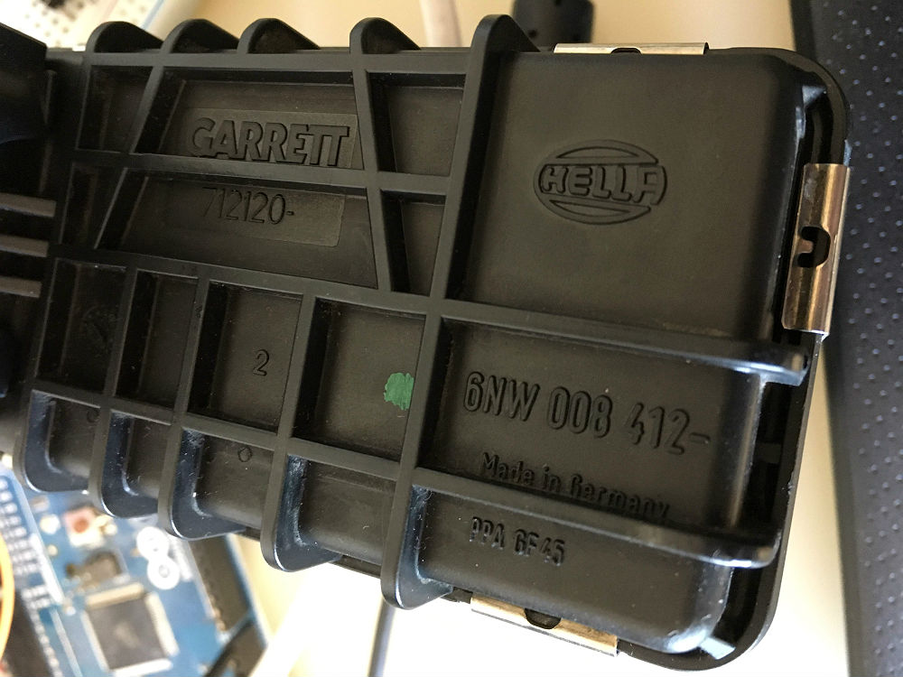
Once put back together, it was time for some googling around. The actuator i have is labeled 6NW 008 412, which is the same number as most of these actuators seem to be. Another identification found on the plastic case is the number 2, and there is also a G-****-tag on the metal casing, these two identify the OEM manufacturer and type of the actuator.
It seems there are two ways of controlling a actuator like this, PWM and CAN. The control method depends on how the unit is programmed upon manufacturing, and cannot be easily changed. Some sources tell that the actuator can be controlled with either one, but i tested this with my PWM-controlled actuator, and it definitely didn’t send out any messages on the CAN-bus, as it’s manufactured for a PWM-application.
Actuator Pinout
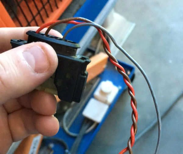
| Pin # | Function |
| 1 | 12V+ |
| 2 | GND |
| 3 | CAN |
| 4 | PWM |
| 5 | CAN |
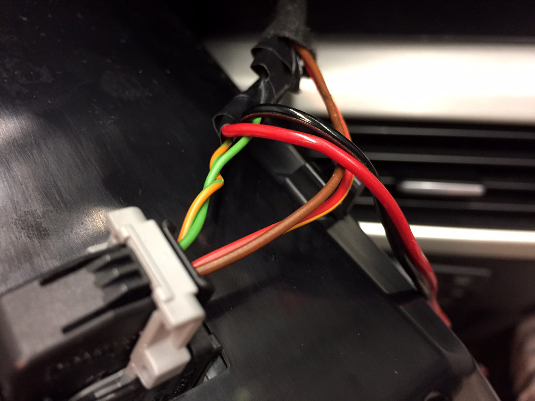
Well, how do you find out which type of actuator you have? In my case it was easy as the connector & a bit of stripped wiring was supplied with the turbocharger & actuator. On the connector, pins 1,2 and 4 were connected, in other words, +12V (red), GND (brown) and PWM (grey). If you don’t have the connector, Google will be your best friend.
Controlling the actuator
The PWM control signal depends on the OEM manufacturer request. Some actuators need a 140Hz PWM signal, while others accept 300Hz. There might also be other frequencies, but these two are the most typical ones on this type of Hella actuator. The signal is of grounding type, which means that the actuator outputs a steady signal on the PWM pin which is then modulated by a microcontroller grounding that pin in a timed sequence to achieve the desired PWM output.
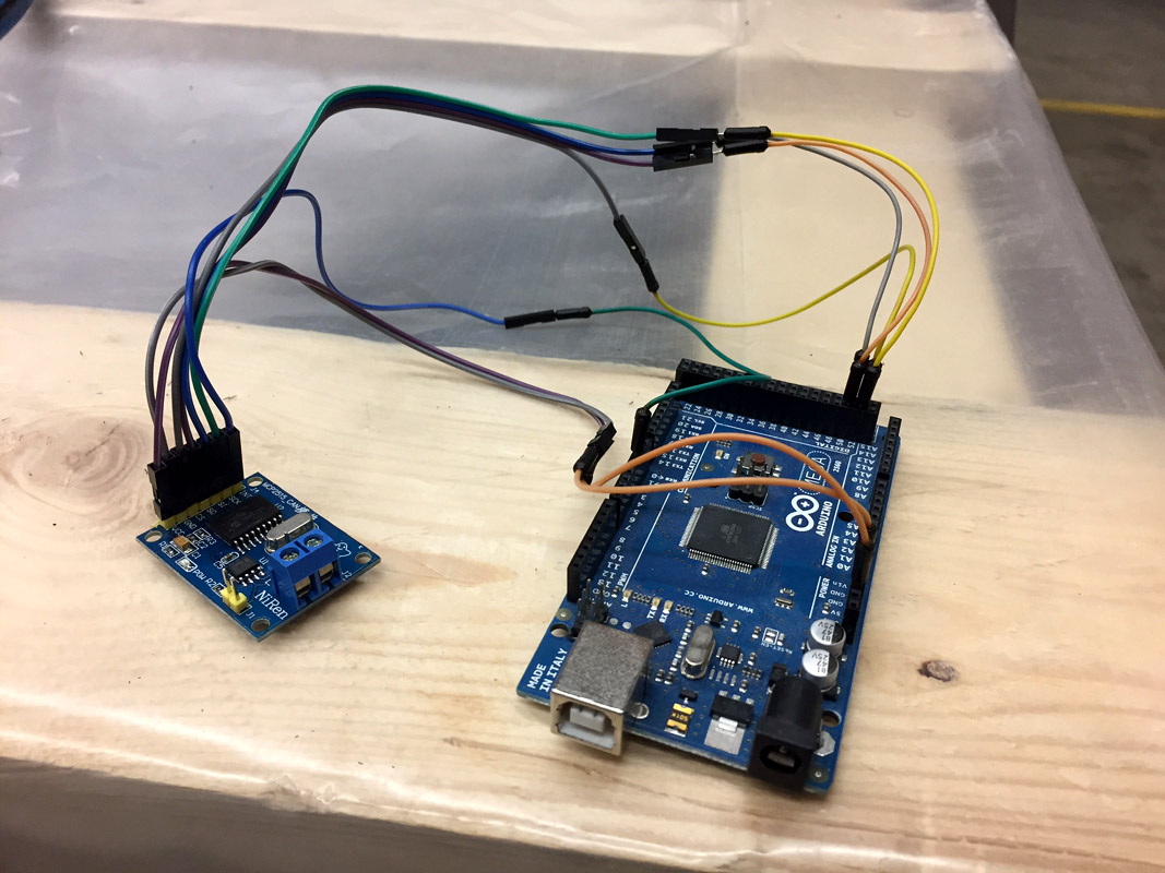
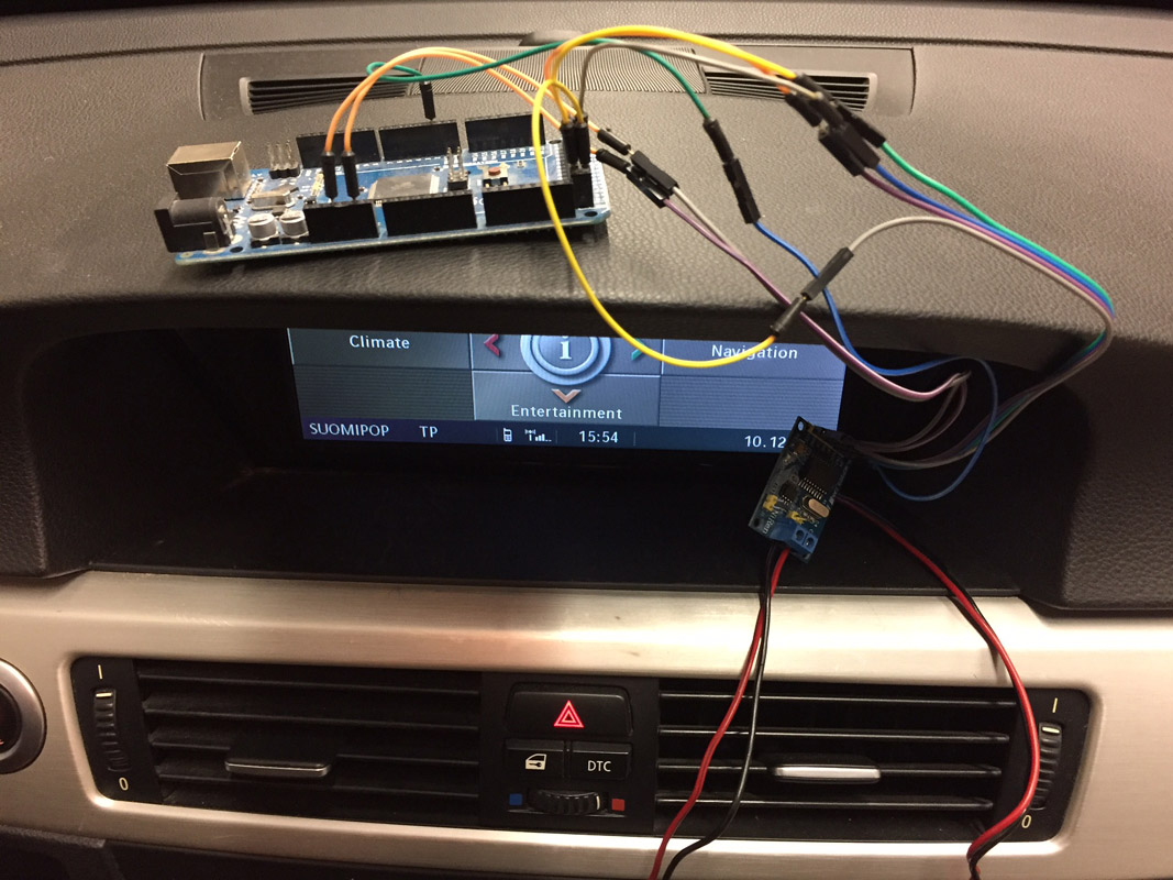
I will ultimately control the actuator with my aftermarket ECU, but for testing purposes i hooked it up to my Arduino MEGA2560. Any Arduino or programmable microcontroller capable of PWM will be just fine though. Using Arduino, there are a couple things that needs to be taken into account:
Wiring
So, for connecting everything you need an Arduino, a transistor, a 1k resistor, a breadboard and some wires.
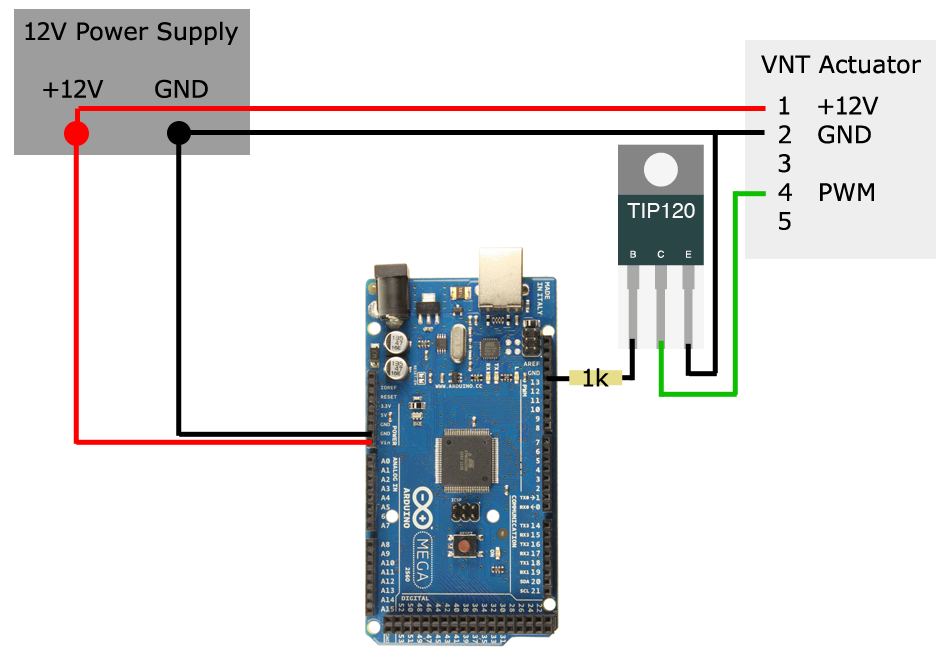
The power supply feeds power to the Arduino and VNT actuator. PWM-signal is applied through a current-limiting 1k resistor to the Base of the TIP120, this is the “control signal” for the transistor. The PWM signal from pin 4 on the actuator is routed to the Collector of the TIP120. When Arduino applies voltage to the Base of the TIP120, current will flow through the TIP120 from the Collector to the Emitter. As the Emitter side is tied to GND, the PWM line will be grounded. This sequence, done in correctly timed cycles, will produce the control signal needed for the VNT actuator to function.
The Code
/*
 * Simple sweep for testing a Hella VNT-actuator @ 300Hz.
 * Uses digital pin 13 for PWM.
 */


void setup() {
  pinMode(13, OUTPUT);
}

void loop() {

// SLOW SWEEP UP
    for (int sweep = 0 ; sweep <=3333 ; sweep += 6) {
  digitalWrite(13, HIGH);
  delayMicroseconds(sweep);
  digitalWrite(13, LOW);
  delayMicroseconds(3333 - sweep);
    }

// SLOW SWEEP DOWN
    for (int sweep = 3000 ; sweep >=166 ; sweep -= 6) {
  digitalWrite(13, HIGH);
  delayMicroseconds(sweep);
  digitalWrite(13, LOW);
  delayMicroseconds(3333 - sweep);
    }


// FAST SWEEP UP
        for (int sweep = 0 ; sweep <=3333 ; sweep += 33) {
  digitalWrite(13, HIGH);
  delayMicroseconds(sweep);
  digitalWrite(13, LOW);
  delayMicroseconds(3333 - sweep);
    }

// FAST SWEEP DOWN
    for (int sweep = 3000 ; sweep >=166 ; sweep -= 33) {
  digitalWrite(13, HIGH);
  delayMicroseconds(sweep);
  digitalWrite(13, LOW);
  delayMicroseconds(3333 - sweep);
    }

}
The result
As seen on the video, the actuator works just fine. It seems that this kind of actuator doesn’t like under 5% or over 95% duty cycle, and will possibly wind itself to start position if those limits are exceeded. Good to know if you’re controlling something critical.
-K-