Hi there!
Lately i’ve been busy working on a way to get some relevant information (like RPM, throttle position, torque, coolant temp. etc) from my 320d, as i want to build my own “info-screen” which will be displayed on the iDrive-display of my car.
The best way to get extensive amount of engine operational data on any E6x/E8x/E9x would surely be to hack into the DME/DDE K-Line and send BMW-specific polls (in the same way that INPA/ISTA/Testo works using EDIABAS), and at first i tried to go that way, but couldn’t get the communication between my Raspberry Pi and the DDE6.0 on K-Line to work, so i decided to try the K-CAN-bus instead. It turned out to be really simple, using only an Arduino and an MCP2515-CAN-module.
My setup
- Arduino Mega2560
- MCP2515 CAN-module
- some jumper wires
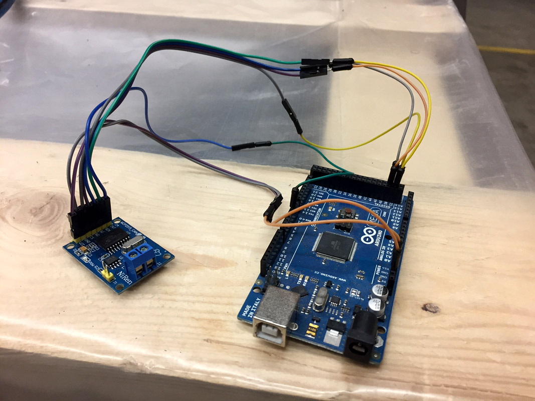
Connections
Name----Mega2560---MCP2515

INT-------2----------INT

MISO------50---------SO

MOSI------51---------SI

SCK-------52---------SCK

SS--------53---------CS

VCC-------5V---------VCC

GND-------GND--------GND
I use the Mega2560 for testing, but if i’m about to mount one permanently, i will switch to a smaller board. I usually go for the Arduino Pro Mini, which is small in size but has a decent amount of I/O and is easy to program with an USB-to-TTL-programmer. The MCP2515 uses SPI, so it can be connected to about all Arduino-models, only pin numbers will be different.
The finished wiring looks like this:
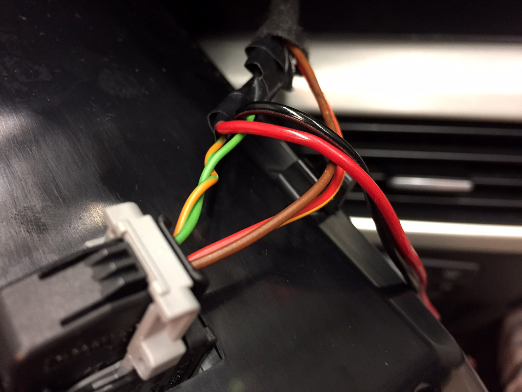
Next, off to find a suitable spot to tap into the K-CAN-bus. I used the wiring at the iDrive-display power connector because i already was familiar with removing the display (really simple, undo 2x TX10 screws and the screen pops out). There are surely other better spots to tap into the wiring, but this is one way to do it.
Wiring for the arduino (Black/Red cable) tapped into the K-CAN.
CAN H+ Green/orange, CAN L- Green:
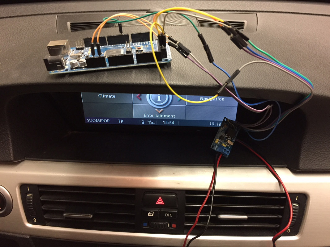
Screen back in, ready to be tested:
Software
Next, the Arduino needs the correct software. Fortunately, there are many suitable CAN-libraries online that seem to work with the MCP2515. I used Cory J Fowlers MCP_CAN_lib. There is an example sketch in the library called CAN_receive which will work on the BMW K-CAN-bus with some minor modifications.
From:
MCP_CAN CAN0(10); // Set CS to pin 10
To:
MCP_CAN CAN0(53); // Set CS to pin 53
Because i’m using pin 53 on the Arduino Mega2560 for CS.
From:
if(CAN0.begin(MCP_ANY, CAN_500KBPS, MCP_16MHZ) == CAN_OK)
To:
if(CAN0.begin(MCP_ANY, CAN_100KBPS, MCP_8MHZ) == CAN_OK)
Because the bus on my pre-LCI E91 is 100kb/s K-CAN (the newer ones from 2007 onwards have D-CAN @ 500kb/s). The frequency change from 16MHz to 8MHz is because my MCP2515-chip has an 8MHz oscillator, your module could be different.
After sketch was uploaded and ignition turned on, there was a nice continous stream of K-CAN-bus data on my serial terminal.
Standard ID: 0x130       DLC: 5  Data: 0x41 0x51 0x2D 0x00 0x01

Standard ID: 0x0AA       DLC: 8  Data: 0xAD 0x81 0xFC 0x00 0x00 0x00 0x84 0x00

Standard ID: 0x1B8       DLC: 6  Data: 0x0F 0xC0 0x83 0x02 0xA0 0x21

Standard ID: 0x4A7       DLC: 8  Data: 0x40 0x52 0xFF 0x01 0xFF 0xFF 0xFF 0xFF

Standard ID: 0x1A6       DLC: 8  Data: 0x00 0x00 0x00 0x00 0x00 0x00 0x60 0xF8

Standard ID: 0x0C0       DLC: 2  Data: 0xFE 0xFF

Standard ID: 0x1B8       DLC: 6  Data: 0x0F 0xC1 0x83 0x02 0xA0 0x21

Standard ID: 0x349       DLC: 5  Data: 0x90 0x1A 0x9A 0x20 0x00

Standard ID: 0x1B4       DLC: 8  Data: 0x00 0xC0 0xE2 0xF9 0x00 0x30 0xFC 0x80

Standard ID: 0x0CE       DLC: 8  Data: 0x00 0x00 0x00 0x00 0x00 0x00 0x00 0x00

Standard ID: 0x1A0       DLC: 8  Data: 0x00 0x80 0x00 0x00 0x80 0x00 0xC8 0x6B

Standard ID: 0x1D0       DLC: 8  Data: 0x61 0xFF 0x42 0xC5 0x00 0x00 0xCD 0xB0
I was surprised how much data is actually passing through all the time!
So how about interpreting the data? That’s something i will write about later. 😉
If you’re in a hurry, this site will get you started in understanding the data in the K-CAN-bus.
-K-